
Getting Started with the LoRa Node Arduino Shield
Our IoT LoRa Node Shield allows you to create an inexpensive LoRa node, compatible with The Things Network, in conjunction with an Arduino or compatible Arduino board. This shield allows quicker prototyping as it has the LoRa stack on the chip. Add sensors, buttons and more to complete your LoRa network!
Features
- Uses RAK811 LoRa Radio with full LoRaWAN Stack embedded.
- Communicates with Arduino over UART only using a total of 3 GPIO pins for the module.
- Support LoRaWAN connections and LoRa P2P modes.
- u.FL connector and on-board antenna allowing different antennas to be used or integrated into enclosures with external antennas.
- Supports Arduino nano or Due format
- Low power – uses less than 50mA during transmission
What you need
- Arduino Board
- IoT LoRa Arduino Shield
- Arduino USB data/power cable
Note: The LoRa Shield will work with any Arduino with a UNO or Nano pinout
Setting up a TTN Device
Step 1 - Login to TTN
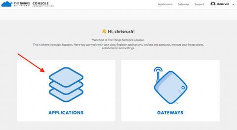
First go to https://console.thethingsnetwork.org
- If not logged in login using your TTN Username and password.
- If you don’t have an account, click create an account and follow the steps to setup a TTN Account

Step 2 - Create an application
- Click on applications
Note: If you have already created an application then you can skip to Step 3
- Then click “add application“

- For application ID use “my-iotlora-application-<Yournamehere>“, in my case it is “my-iotlora-application-chris” or use something unique to you.
- Description: use something like “PiSupply IoT nodes”
- Handler registration use “ttn-handler-eu“
- Click “add Application“

-
Next click payload formats
- Click the custom bar and change it to Cayenne LPP

Step 3 - Register new device
-
Now click “Devices” in the toolbar
- Then “register device“

- Here create a unique ID, in my case I’ve done “chris-lora-shield“
- For device EUI click the two arrows to the left to generate one (we will change this later)
- Then click “Register“

-
In this device, next we want to click “Settings“
- Change the activation method to ABP by clicking the ABP Button (This may be the default setting)
- For development we want to disable frame counter checks, do this by unticking this field at the bottom
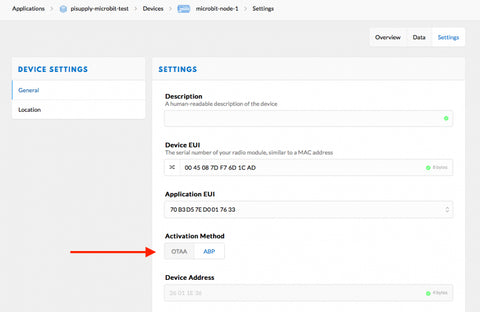
- Now TTN Is ready for our Shield! Keep this page open in a tab for later on
Install RAK811 Arduino Library
Step 1 - Download and install Arduino IDE
First you will need to download and install the Arduino IDE, which you can find at https://www.arduino.cc/en/main/software

Select your operating system and install the Arduino IDE software.
Step 2 - Download & Install RAK811 Arduino Library
Head over to our GitHub page https://github.com/PiSupply/RAK811-Arduino, click the “Clone or Download” button on the right hand side to download the zip file of the RAK811 library.

Unzip the downloaded file on your computer and then place the unzipped folder into the Arduino Libraries directory. Usually this is located in “Documents” or “My Documents”.
Connecting your Hardware
Connect the LoRa Shield to your Arduino board according to the images below.
Arduino UNO

Arduino Nano

Arduino Due

Software Sketch
Firstly, open up the Arduino IDE application. You should see something like the below image, an empty sketch.

Setting the baud rate
We have experienced issues with the default baud rate of 115200 so we need to set a new baud rate of 9600 using the provided example.
In the Arduino menu select File > Examples > RAK811-Arduino-master > Setbaudrate
Now go to Tools > Boards and select your Arduino board from the drop down list

Select your port form the port list in Tools > Port
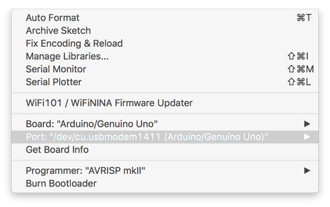
Finally hit the upload button to upload the sketch to your Arduino board.

Your First Example
In this example we are going to use the ABP example provided in the library. Open up from the Arduino menu File > Examples > RAK811-Arduino-master > JoinNetworkABP
Before you upload your sketch to the Arduino board you will need to fill out your credentials which you can find in the TTN Console for the device we setup earlier. Simply copy and paste these into the sketch.

Finally upload your sketch to the Arduino board and you should see packets being sent to your Gateway in the TTN console under “Data”.

Setting your frequency
To change the frequency on the LoRa node we have to be able to send what is known as AT serial commands and we can do this through the Arduino IDE.
In the Arduino IDE open up the “Serial Passthrough” example File > Examples > RAK811-Arduino-master > serialpassthrough
Upload the sketch to the Arduino board and then open up the serial monitor.

In the serial window enter the following command to change the frequency:
at+band=EU868
If you get an error message, ensure that the line ending is set to “Both NL & CR” in the bottom right hand corner.
You can see a full list of frequency bands here – https://www.thethingsnetwork.org/docs/lorawan/frequency-plans.html
NOTE You may experience issues with US915 and AU915 depending on the regional configuration and gateway coverage. As standard up to 64 channels are set as default.
For the things network we recommend that you set the following configuration lines as these will disable all but the 8 that TTN is setup to use.
To set the configuration it’s recommended that you send it via the serial passthrough and serial terminal.
at+set_config=ch_mask:0,FF00
at+set_config=ch_mask:1,0000
at+set_config=ch_mask:2,0000
at+set_config=ch_mask:3,0000
at+set_config=ch_mask:4,0000