Getting Started with the Pi Supply Switch
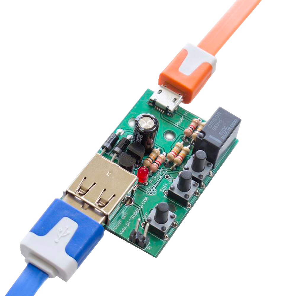
The Pi Supply Switch is the solution to all of your Raspberry Pi power management problems. It is an intelligent, ATX style power supply switch for the revolutionary Raspberry Pi computer. It allows you to leave all of the power wires from the wall wart all the way through to the Pi permanently connected with just the quick push of a switch to turn the power on or off.
This guide is a set of assemble instructions for the Pi Supply Switch version 1.1. Follow the guide step-by-step to assemble and connect to your Raspberry Pi.
Whats in the box?

- 2x 22k resistor
- 2x 10k resistor
- 2x 1k resistor
- 2x 1N4001 diode
- 2x BC548 transistor
- 1x 3mm red LED
- 1x 220uF capacitor
- 3x tactile switches
- 1x G5V-1 5 DC relay
- 1x 2-pin throughhole header
- 1x USB A receptacle
- 1x USB to micro USB cable
- 2x F-F Jumper wires
- 1x Pi Switch PCB
Whats you will need
Below is a comprehensive list of tools you will need to assemble the Pi Supply Switch. If you are not confident on soldering this your self then it is recommended to see advise from someone who knows how to solder or alternatively seek a local hackspace in your area.
- Soldering Iron
- Solder 60/40
- Snips
- Helping Hand (optional)
- Blue-tac/White-tac (optional)
How to assemble your Pi Switch
Step 1 – First we are going to insert the resistors into their places on the PCB. Resistors are not polarised, which means that can be inserted in any orientation when placing them in the PCB. Insert the resistors into the following labelled holes:
- R1 and R2: Resistor 22k (Red, Red, Orange, Gold)
- R3 and R4: Resistor 10k (Brown, Black, Orange, Gold)
- R5 and R6: Resistor 1k (Brown, Black, Red, Gold)
Once inserted you can either hold the resistors in place with some blu/white-tac or you can bend the pins on the reverse side.
Solder the resistors to the board and then snip the ends away.

Step 2 – Now lets solder the diodes to the PCB. There are two diodes which insert into D1 and D2, then there is the red LED which connected to D3. The two diodes and the LED are polarised which means they have to be inserted into the PCB the correct way round otherwise the circuit twill not work because a diode only allows current to pass through in one direction but not the other. On two of the diodes there is a white band and this end must be inserted into t eh square solder pad of D1 and D2. With the LED there is a long leg (anode) and a shorter leg (cathode), the sorter leg should be inserted into the square solder pad of D3.

Step 3 – Now we can insert the two transistors into Q1 and Q2. Both flat sides of the transistors should be facing each other in the centre, as per the outline on the PCB. Also insert the relay into the RL1, where it will only fit in a particular orientation so just rotate it until it slots into the holes.
Note: Be careful not to solder the pins together on the transistors as the legs are close together. Try to put small amount of solder on at a time.

Step 4 – Insert the three switches into “off”, “soft_off” and “on” of the PCB. The switches can only be inserted in a particular orientation but it doesn’t matter which end goes in, as they are essentially the same on both sides of the switch. Once you have done that you can insert the capacitor, which is polarised component. The cathode side of the capacitor can be identified by the white stripe down the side or the shortest leg. Insert the cathode leg into the hole that is closest to the diodes.
Note: You may have to bend or wiggle the switches in place
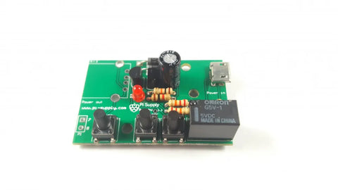
Step 5 – Finally you can insert the USB socket and the then the 2-pin header. The 2-pin header should have the shortest pins inserted to the top of the PCB and the soldered underneath. The USB socket has two much larger holes for holding in the USB socket in place to the PCB, these have no functionality within the circuit but still must be soldered to the PCB.

For connecting the two pin header to the Pi, they are labelled 7 and 8. Pin 8 has to go to pin 8 on the GPIO header on the Pi. Pin 7 can go to any other Pi GPIO port, but since 7 is next to 8 we thought that would be easier.
Installing the Software
Before you connect your Pi Switch to your Raspberry Pi you must install the software. It is important that the software is installed prior to connecting the Pi switch otherwise you will experience issues.
Step 1 – Connect your mains power supply to the Raspberry Pi and boot it up to the Desktop.
Step 2 – Once your Raspberry Pi has booted you will need to connect to the internet either using the Wi-Fi connection or directly plugin in an Ethernet cable to your Raspberry Pi.
Step 3 – When you are connected to the internet open up a terminal window and type in the following command or copy and paste the command from our GitHub repository:
curl -sSL https://pisupp.ly/piswitchcode | sudo bash
Step 4 – Once the software has finished installing it will prompt you to shutdown the Raspberry Pi. Once the Pi has shutdown you can remove the power.

Connecting your Pi Switch to your Raspberry Pi
Step 1 – First step is to connect the jumper cables from the 2-pin header on the Pi Switch labelled “7&8” to the Raspberry Pi. Connect the header 7 o the Pi switch to Raspberry Pi pin 7 and then pin 8 on the Pi Switch to Raspberry Pi pin 11.
Note: It is important that they are connecting to the correct pins on the Raspberry Pi

Step 2 – Connected the provided USB cable from the Pi Switch to the Raspberry Pi’s micro USB port.

Step 3 – Finally connect your mains power supply to the Pi Switch micro USB port.

Step 4 – Now you can switch ON the Raspberry Pi using the “on” switch and after a few moments you should see the red LED light up to indicate that it has connected to the Raspberry Pi service.
To switch the Raspberry Pi OFF you can either do a hard shutdown by pressing the “off” switch or you can shutdown the Raspberry Pi safely by pressing the “soft_off” switch. You can also RESET the Raspberry Pi by holding own the “soft_off” switch.
Raspberry Pi 3 Users
If you use the Pi Supply Switch with the Raspberry Pi3 you may experience under-voltage issues and unexpected power off.
Under-Voltage
In order to solve the under voltage problem it is advisable to use shorter USB cable. 15-30 cm with a thickness of 22 AWG should solve the issue. These types of cable are generally the ones used for phone charging and should be easily found in various shops.
Alternatively you could modify the Pi Switch as indicated in the picture and use some dupont link cables to attach the Pi Switch directly to the Raspberry Pi header.

Power Off
The Raspberry Pi3 has also changed the way the on board UART works. Because of that you may find that the Raspberry Pi could switch off within two minutes of it powering up. To solve this please refer to our GitHub repository for the new Jessie compatible software and an updated connection scheme as shown in the picture below.
Please install the code before you connect the switch.

Below is a video on how to assemble the Pi Supply Switch.